Manage & Use MediaWeb PACS

Acquire, store and manage digital images from intraoral cameras, x-ray scanners, sensors, & OPG devices.
Launch from Dental4Web
 Click here for instructions
Setup Preferences
Display any charting information assigned to an image in the View window.
- On the Landing page
- Click the drop list > Preferences
Show Chart Position in Viewer
Show Chart Position in Viewer option is OFF by default
- Tick the OFF Checkbox
- Show Chart Position in Viewer is now ON
- Click Save
- The option will be saved and the charting information will be displayed under the date/time the image was taken
Default modality for Imported images
Default Modality for Imported Images will be assigned by default to all images imported by the current User.
- Currently the default setting is OT - Other DICOM modality.
- Drop list to select a modality
- Click Save
Examination page without true image preview
Speed up the upload process of large images such as high-resolution colour photographs and reduce the Internet browser demand for a PC memory.
- Remove tick from High re Preview on Examination checkbox
- Click Save
 Note: Once unchecked the images won’t be loaded onto the examination page - their thumbnails will. This is recommended for multiple large colour images’ processing as it will significantly improve performance.
 Landing Page Explained
Images
The IMAGES page is the default landing page when MediaWeb PACS is opened from Dental4Web Patient pages
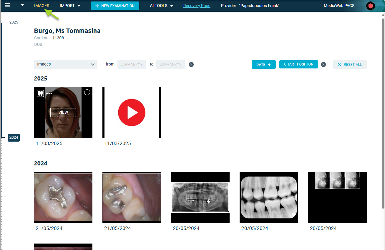
Title Bar
- Preferences: Display any charting information assigned to an image in the View window
- IMPORT: Used to import either “normal” images / videos or DICOM images
- NEW EXAMINATION: Initiates CMScan Web to capture images that are captured from hardware devices
- AI TOOLS: Assess and detect dental pathology in x-rays via the Second Opinion interfaceSecond Opinion Functions for MediaWeb PACS users
- Recovery Page: Once an Image is deleted from IMAGES, they are moved to the Recovery Page automatically. Within the recovery page the selected image can be recovered
- Provider and Location names
- Click on the MediaWeb PACS Logo to show MediaWeb PACS version information, etc
Patient Information and Parameters
- Patients Name, Card No and DOB
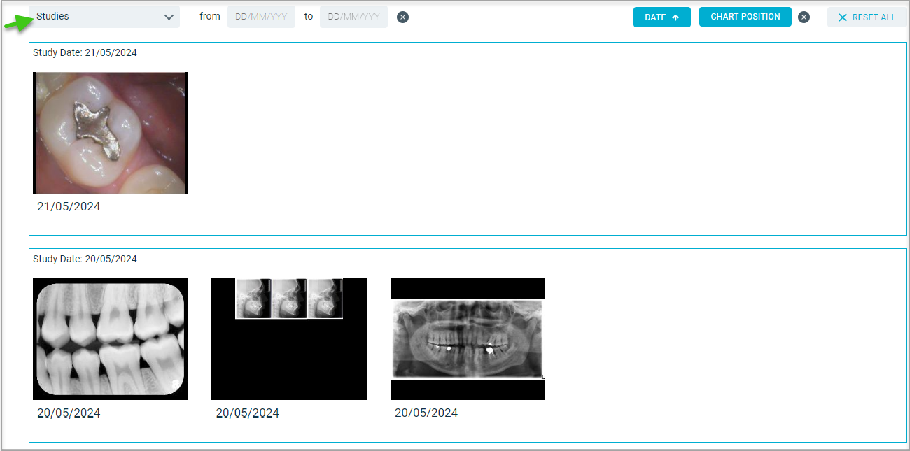
- The mode of viewing images, either Images (the default) as shown or by Studies
- TimeLine viewer: year range timeline can be viewed/ selected on the left.
- Selecting a year will open that years studies and all later years (example: select 2023, then year 2024 & 2025 will also be opened)
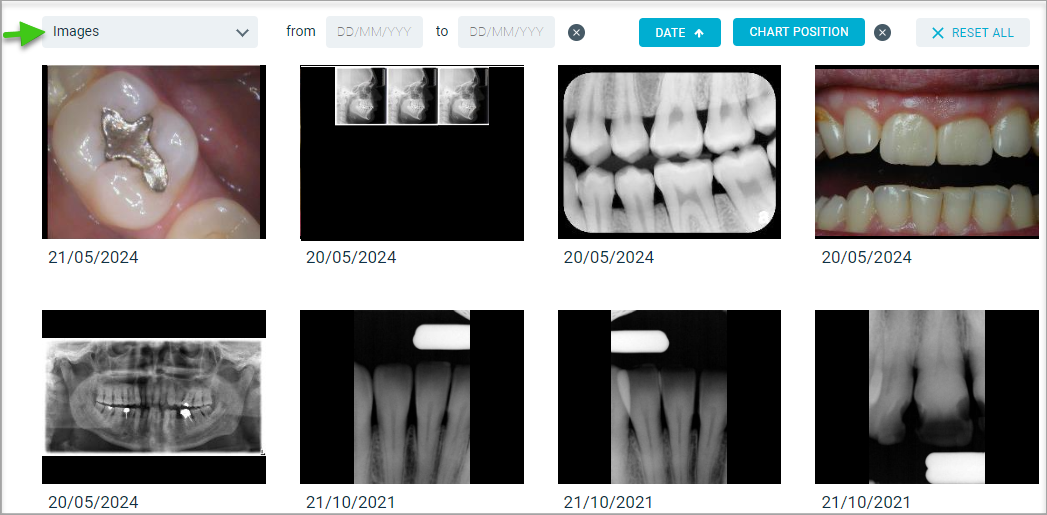
- from / to: Filters images by date range. By default, nothing specified, all images will be displayed. Options are:
- Specify a from and to date – will display a limited date range
- Specify only a from date – will display all images from that date on
- Specify only a to date – will display all images up to that date
- DATE: Enables the images to be displayed in ascending or descending sequence
- CHART POSITION: Filters images by Charting. Pressing “x” will rest filter default. i.e. no filtering
- RESET ALL: Resets all Filters to their default settings
X-rays/Images
Images: Listed individually with the date taken
Studies: Listed in study groups
Note: All images taken in 1 day for the selected patient are saved as a single study
Note: All images taken in 1 day for the selected patient are saved as a single study
Individual Image / Video Selection
When the mouse hovers over an image / video, 4 options are displayed
Image Properties
- Click the tooth icon to display the image properties
- Charting information – this can be modified
- Date/time taken
- Dentist
- ID
- Colour depth
- DICOM modality
- Notes – this can be modified
- The arrows (< and >) allow scrolling through the images
Print, Download, Copy, Delete
- Click the 3 dots for dropdown, select to Print, Download, Copy, Delete the single image
- Images are downloaded to Browser’s download folder
View Image/Xray
- Click on VIEW to open the image in Editor for examination and/or enhancement
- Click on the selection circle to select multi images
- Open in Editor, Printing or Downloading is selected by clicking the appropriate icon
- By clicking on “x” it will revert to the Images page with the selections cleared
DICOM (Digital Imaging and Communications in Medicine)
The type of equipment or imaging method that produces the images.
What is DICOM

DICOM (Digital Imaging and Communications in Medicine) files are comprehensive data containers, not just image files.
They combine image pixel data with a structured "header" that contains extensive metadata, making it impossible to accidentally separate the image from its patient or study context.
DICOM files contain not only the image itself, but within are embedded details like Patient Name, ID, DOB, Date/time and many more etc
DICOM Modality
Why does the correct Dicom Modality matter?
Correct image type = correct workflow
If an image is saved under the wrong modality, it might not show up in the right place in their software. For example, a CT scan accidentally saved as a normal X-ray could cause confusion or delays.
If an image is saved under the wrong modality, it might not show up in the right place in their software. For example, a CT scan accidentally saved as a normal X-ray could cause confusion or delays.
Smooth integration with other systems
Practices often send images to specialists, labs, or hospitals. The receiving system relies on the modality tag to know what kind of image it’s getting. Wrong modality = problems sharing or viewing.
Practices often send images to specialists, labs, or hospitals. The receiving system relies on the modality tag to know what kind of image it’s getting. Wrong modality = problems sharing or viewing.
Compliance and patient safety
Properly labelled images reduce the risk of clinical mistakes. Staff can be confident they’re looking at the right type of scan for the right patient.
Properly labelled images reduce the risk of clinical mistakes. Staff can be confident they’re looking at the right type of scan for the right patient.
Troubleshooting made easier
If something isn’t displaying properly, one of the first checks is whether the modality is set correctly. If staff understand the basics, they can spot issues quicker before escalating.
If something isn’t displaying properly, one of the first checks is whether the modality is set correctly. If staff understand the basics, they can spot issues quicker before escalating.
IO – Intraoral X-Ray
- X-Ray sensors (MediaRay Plus, Kodak RVG, Sirona XIOS XG etc.) and Phosphorus plate scanners (MediaScan, Digora Optime, Kodak CS7600/CS7200 etc.)
- Default of all intra oral X-Rays
CR - Computed Radiography
- Only Phosphorus plate scanners (MediaScan, Digora Optime, Kodak CS7600/CS7200 etc.)
- Setup only if specifically requested
ES - Endoscopy image
- Use only and exclusively for ALL intra oral cameras such as MediaCam Pro, MediaCam 2, Sopro, Mouthwatch etc
PX – Panoramic
- Use for all OPG devices such Soredex Cranuss Novus, Planmeca ProMax, Vatech Pax -I etc
- Use only if confident this is the OPG (Panoramic device) or a COMBO one (CBCT+OPG)
DX – Digital radiology
- Can be used only in case there is no information on the device except it is a digital X-Ray machine
XC – Digital Photographic image
- Cannot be setup for automated apply
- It should be manually entered on each image import in the Examination page
OT – Others
- The default modality for the import.
- Used when it is not possible to identify the correct one
Using MediaWeb PACS
Export / Import Images
Export Images in DICOM format from MediaWeb PACS
- Select the Image:
- Click the Export Icon found in the navigation menu on the left
- Read the Warning in the Export DICOM window
- Click CANCEL or DOWNLOAD
Import a DICOM image to MediaWeb PACS
- From the IMAGES page:
- Select DICOM from the IMPORT dropdown
- Drag and Drop or Click BROWSE FILESCT (Computer Tomography aka 3D)
MRI and PET – may be imported; but it is not recommended - Once the image is passed to MediaWeb PACS, the following scree is displayed
- Click USE DENTAL4WEB PATIENT DETAILS for D4Web details to be used
- Click USE DICOM PATIENT DETAILS to display Patient, Gender and DOB
- Patient, Gender and DOB details can be overwritten
- The Study date cannot be altered
- If multiple images are imported the above window is repeated for each image
Import 3D Images
3D (CBCT) volumes can be imported into MediaWeb PACS (MWP), and viewed using the Multi Planar Reconstruction (MPR) Viewer.
Before initiating the import ensure you are in the correct patient to receive the 3D volume.
- From the IMAGES page:
- Select 3D from the IMPORT dropdown
The following is displayed - Click BROWSE FILES
- Browse to appropriate location that holds the slices that for the volume to be imported.
- Select all the slices; and click Open
As the slices are imported they are validated
When the import is completed the following is displayed… - Click USE DENTAL4WEBPATIENT DETAILS or USE DICOM PATIENT DETAILS
The following is displayed when the volume is loaded/opened… - Once the study is loaded, the following is displayed:
- Click 2D MPR to open the MPR viewer
The MPR Viewer will be displayed.
Import STL Images
This feature available in MediaWeb PACS commencing build 1.036
- From the IMAGES page:
- Select STL from the IMPORT dropdown
The STL model is processed the same way as an image - Click IMPORT
The basic manipulations are possible with the imported STL model, however without saving.
Operations available with STL:
Export to STL file (both on the Patient and Viewer pages)
Export to DICOM file (on the Viewer page only)
New Examinations
Multiselect and update on the Examination page
- Click on NEW EXAMINATION icon
- IMPORT > Select Images
- Select the images
- Multi select
and apply manipulations such as Dental charting, rotations and flips, Notes and DICOM Modality to all of them at once.
- Click SAVE when complete
Important! Image filters as well as the Windowing tool cannot be applied to multiselected images on the Examination page even if a single image has a multiselect checked. These can be applied individually only by a click on the image to open it in full (high) resolution because the Windowing tool as well as the filters requires full resolution image to make the changes. Image Enhancement Tools
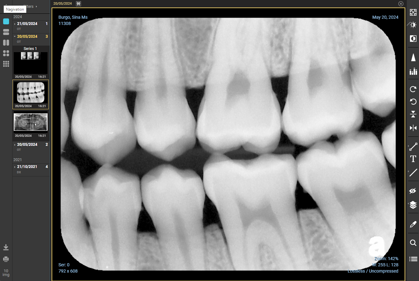
Hover mouse over image to enable VIEW
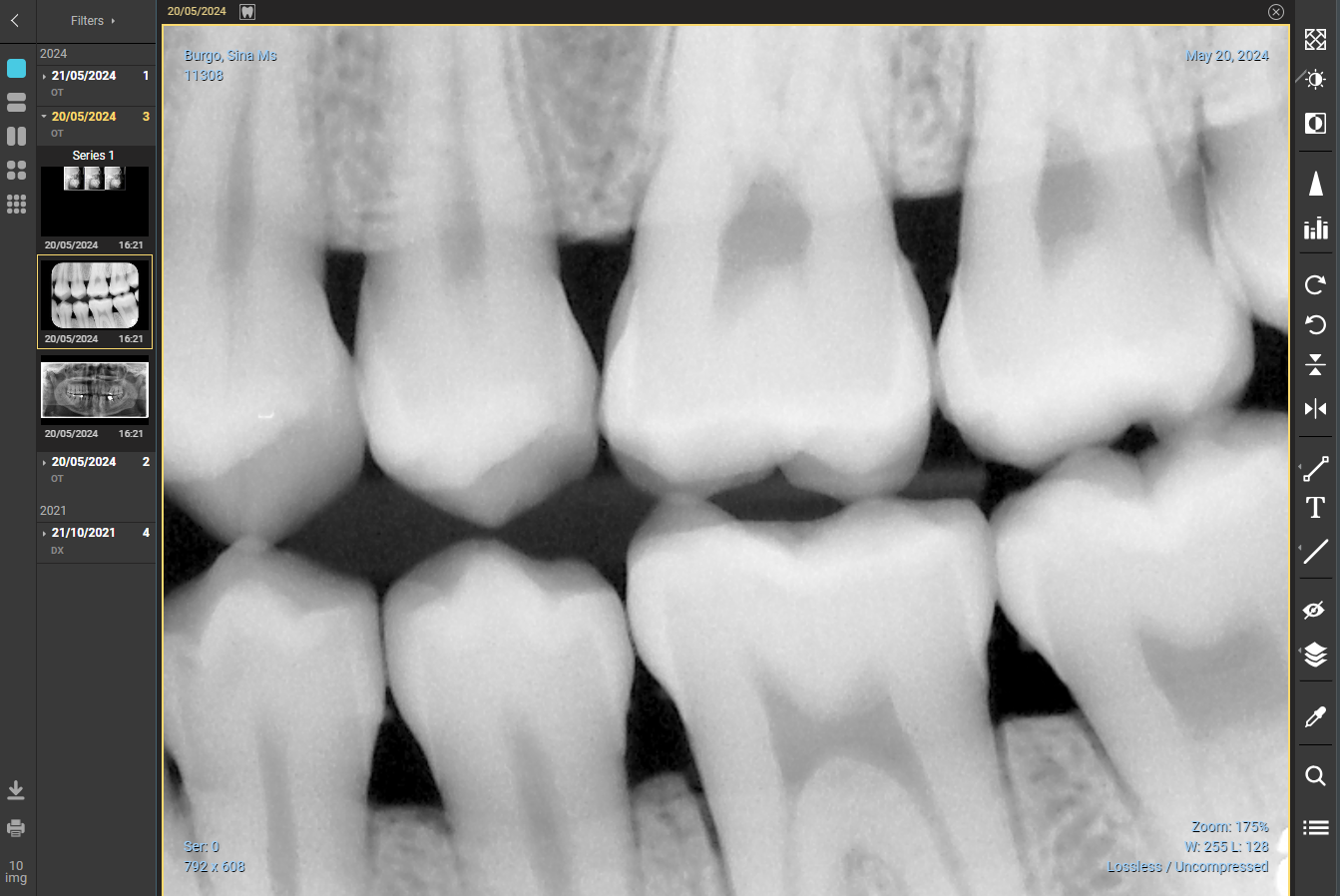
- Click VIEW
- When an image is opened, the following editor is displayed, the toolbar has been highlighted
- Double click on the image to alternate between the normal view and maximised viewOnly Annotations can be saved for an image, see list below. Other changes to an image are not saved
Auto Active Tools
Three tools are active when an image is opened, before any clicks: Zoom, Pan and Levels. (Levels is the default tool)
Zoom
- Use the mouse wheel to zoom in or out of an image, this function is always active
Zoomed in
Zoomed out
Pan
“Pan” enables zoomed images to be navigated
- Click and hold the right mouse button down
- Drag the mouse, with the right mouse button down, to navigate the image
- Release mouse button when finished
After Zooming
After Panning
Levels 
(The default tool) Changes window Level and window Width values, i.e., Brightness and Contrast
- Click the tool
- Hold the left mouse button down and move the cursor up/down and/or left/right to adjust the changes window Level and window Width values
- The changes are reflected in the changes window Level and window Width shown in the bottom right of the display
- Deselect the tool
Customise Preset Levels in the viewer page
Available in MediaWeb PACS commencing build 1.036
- To enter the Window Width & the Window Centre
- Click Add.
- The default name is created
- Rename the Level
- Click Rename
- Type in the new name
A list of preset/ renamed levels can be viewed and selected using the drop list
Other Tools found in the Toolbar
An image can be manipulated by using the various tools in the Toolbar
Save 
Save presentation state. The Save icon is used to save changes that are made to the image, it is greyed out until a change is made.
- Make changes to the current image/xray
- Click Save
- All changes made to image will be retained and seen when opened later, the icon will be greyed out.
After a changed image has been saved there is no "undo" function. Click Show Original slider, located in the top left corner, to revert to the original image.
Reset 
The Reset icon reverts the image to its original state, i.e. all changes are reversed.
When the image has been reverted the Save icon remains greyed out until/if the restored image is Saved.
Fit the Frame 
Click the Fit the Frame tool to immediately restore the whole image to be visible and fill the display window, i.e., as it was initially displayed
Before
After

Before
After
MPR view 
A combined layout tool to display both 3D and MPR images.
- Only available when 3D or MPR images are selected in viewer.
- Available in MediaWeb PACS commencing build 1.036
To switch to this layout:
- Click the MPR+3D
Once selected it comes up the following layout
3D view adjustment functionality
The icon  is used to toggle between Windowing control and 3D image manipulation by the mouse.
Allow for soft tissues to be visible
Filter the soft tissues to have the bones and teeth structure to be visible
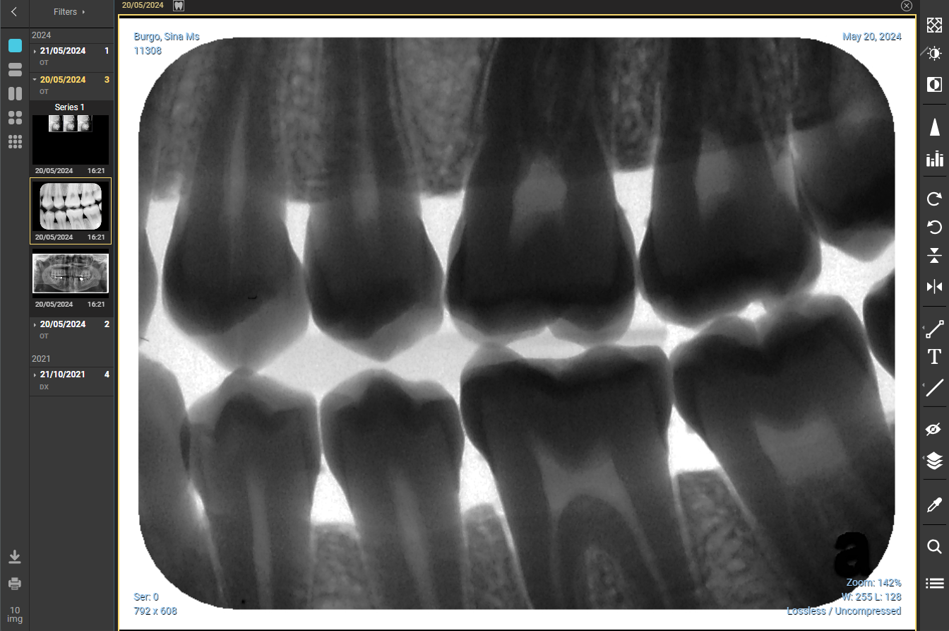
Invert 
Click the Invert tool to immediately invert or reverse the image, clicking again will revert the image to how it was previously
Before
After
Before
After
Sharpening tool 
The Sharp tool is double edged; used correctly in can be very useful in “improving” an image, if used too aggressively it can remove detail and make the image less useful. It is advised to only use the least amount of sharpening necessary
When the Sharpening tool is selected is displays the following dialogue:
When the Sharpening tool is selected is displays the following dialogue:
- Radius is the aggressiveness of the sharpening, the higher the number the more aggressive or more impact the sharpening will have on the image
- Strength is amount of sharpening to be applied at the given Radius
Before sharpening
Select & adjust Sharpening
After Sharpening
Rotate 
When landscape images are rotated, they are automatically resized to show the complete image.
- Rotate Right : Each click of the Rotate Right tool will immediately rotate the image 90 degrees to the right (clockwise
- Rotate Left: Each click of the Rotate Left tool will immediately rotate the image 90 degrees to the left (anti-clockwise)
Before
After Rotate Right
After Rotate Left
Note: Second Opinion users.
Once the image rotated or flipped, it is synchronised to the Pearl integration page.
The image adjustment occurs with a delay of ~30 seconds, and the updated results are received from Pearl in ~60 seconds after the rotation has been applied
Flip 
- Flip Horizontally: Each click of the Flip Horizontal tool will immediately horizontally flip (mirror image) the image
- Flip Vertically: Each click of the Flip Vertical tool will immediately vertically flip (mirror image) the imageBeforeAfter Flip HorizontallyAfter Flip Vertically
Note: Second Opinion users.
Once the image rotated or flipped, it is synchronised to the Pearl integration page.
The image adjustment occurs with a delay of ~30 seconds, and the updated results are received from Pearl in ~60 seconds after the rotation has been applied
Measure Annotations 
When the measurement tool icon is clicked, the following options are displayed
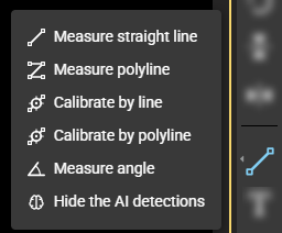
- Measure straight line – measure a single segment line
- Select the tool
- Single left click on the starting point
- Move to the end point of the measurement and single left click
- The measurement will be shown
- Repeats steps 1b to 1d if any further measurements are needed
- When finished de-select the tool
- Measure polyline – measure a multi-segment line
- Select the tool
- Single left click the starting point
- Move the mouse to each intermediate point and single left click
- At the last point double left click
- The measurement will be shown
- When finished de-select the tool
- Calibrate by line – allows an images resolution to be set (if necessary), requires something of known length to be used as the basis for the resolution
N.B. – the result will only be as accurate as the calibration - Select the tool
- Single left click at the starting point of the known measurement
- Move the mouse to the end of the known measurement and single left click
- Enter the known length of the line drawn to calibrate the image
- The following is the result using the new resolution
This is entering the length of the line drawn to set the calibration i.e. 4mm - Click CANCEL or CONFIRM
- Calibrate by Polyline - measures a multi-segment line and allows an images resolution to be set (if necessary)
- Measure angle – measures a simple angle
- Select the tool
- This requires three single left mouse clicks to reach the end point
- The first is at the end of one the legs that defines the angle
- The second is at the apex of the two legs i.e. the point of the angle
- At the last point double left click
- Repeat step for and subsequent angles, if needed
- Hide the AI detections (for Second Opinion users only)
- Select this option if detections found in Second Opinion should be hidden
Draw a measurement line over a calibration Line
- Calibrate the image. E.g. Use an endodontic file (of known length) and calibrate by line/polyline
- Lock the calibration line, double left click the line and click the open padlock to lock the line
- Draw another line that traces the required distance, this line will use the calibration as set above
- When needed the locked line can be unlocked, and if necessary deleted.
Text Annotation 
The Text annotation allows a single line of text to added to the image
To Add Text:
- Select the Text tool
- Click where on the image the text is needed
- Enter the text
- Click CONFIRM or CANCEL
- Once confirmed, the text is visible at the selected spot on image
- When finished de-select the Text tool
To Format Text:
- Change colour of text
- Click on the colour icon and select from the available colours
- Click CONFIRM or CANCEL
- Change the font size
- To select font size, click and select from the options in the drop list
- Click CONFIRM or CANCEL
- Lock the text
- Click the lock icon
- Click again to unlock
- Click CONFIRM or CANCEL
- Delete the text
 There is no warning & deletion is not reversable
 - Click the Delete (bin) icon
Draw Shapes
When the Draw Shape Annotation tool is selected the following options are displayed.
Draw Shapes are used to bring attention to an area (highlight/mark up)
Draw a temp line - draws free hand shapes
Note: This is a temporary annotation used for demonstration purposes and is not saved
- Select the tool
- Move mouse to the starting position
- Click and hold the left mouse button down
- With left mouse button down draw shape using mouse
- When finished release left mouse button
- Repeat steps if further lines are required
- When finished de-select the tool
Draw a line – draws free hand shapes
- Select the tool
- Move mouse to the starting position
- Click and hold the left mouse button down
- With left mouse button down draw shape using mouse
- When finished release left mouse button
- Repeat steps if further lines are required
- When finished de-select the tool
Draw an arrow – draws an arrow
- Select the tool
- Move mouse to where the arrowhead is to be located
- Click and hold the left mouse button down
- With left mouse button down draw the arrow using mouse
- When finished release left mouse button
- Repeat steps 2b to 2e if further arrows are required
- When finished de-select the tool
Draw an Ellipse - draws (ovals, circles) shapes
&
Draw a rectangle - draws (rectangular, square) shapes
To show the average density of the area within the shape, in Hounsfield units (HU):
- This density measurement is only accurate for CT images where they are recorded in DICOM format
- Intraoral X-rays, OPGs etc. don't have the same density data as CT/CBCT (they’re just 2D images with pixel brightness/contrast), as such, these measurement tools can still be used to highlight or mark up images, but the “density” values shown are not reliable for diagnosis.
See https://radiopaedia.org/articles/hounsfield-unit for Hounsfield Unit information
- Select the tool
- Move mouse to the starting point of the shape
- Click and hold the left mouse button down
- With left mouse button down draw the required shape
- When finished release left mouse button
- Repeat steps 2 - 5 if further ellipses / rectangles are required
- When finished de-select the tool
Filter 
The Filter tool allows pre-defined filters to be applied to an image and/or create new filters.
Probe 
Displays the tissue density in Relative Density
- Click the tool to enable it
- Move the mouse over the image to the Relative Density at the selected area
- Click the tool to deselect it
Flashlight 
Enables zoom mode to just a small part of the image as if it’s spotted by a flashlight
- Click and hold the left mouse button and navigate over the image to display a magnified view
- When finished release the left mouse button
List 
This is multi-function tool
- Will display all annotations created for all images for this patient
- Click Save Annotations to save any unsaved annotations, a confirmation message will appear
- Clicking an annotation gives the option to delete it
- Clicking an annotation on another image will open that image, after clicking annotation for Image 2
Move, Delete, Lock or Format Annotations
Once shapes (lines, arrows, ellipse, rectangles) have been added, the user is able to move, delete, lock and format.
- Move an annotation’s shape
- Once an annotation is drawn, move the mouse (+ & o) to the drawn shape
- Click and hold the left muse and drag to new position
- Unclick the left mouse when in correct position
- Delete an annotation
- Move the mouse to the annotation and click
- Click the Delete icon
- Lock an annotation
- Move the mouse to the annotation and click
- Click the Lock icon
- Repeat to unlock
- Format (Colour, font size line width) an annotation
- Move the mouse to the annotation and click
- To select colour, click and select from the available colours
- To select font size, click and select from the options in the drop list
- To select line type, click and select from the drop list
Recovery Page
Once an Image is deleted from IMAGES, they are moved to the Recovery Page automatically.
Within the recovery page the selected image can be recovered
- Select the Recovery Page from the toolbar
- When the Recovery page is opened the following message is displayed (bottom right)
- Click the circle at the top right corner of the images / videos to be recovered.
- Click RECOVER SELECTED
- The recovered image is now found back in the IMAGES page
Note: Images / Videos added to the Recovery page and recovered to the IMAGES page are always dated as per the original date of the Image / Video
Downloading & Printing
Single Images
Single images can be selected for Printing or Downloading.
- The 3 dots appear when you hover mouse over the image.
- Click either Download or Print
Download
- When Download is selected, the following displayed
- Gives the option to:
- Set the filename of the downloaded file (this could include the Study date inf needed)
- Change the file type from JPG (default) to PNG
- Add the following as text on the image:
- Patient name
- Patient ID – Dental4Web card number
- Patient DOB
- Study Date
- Text options – Colour, Size, Bold, Italic, Position (Schema)
- Click CANCEL to quit the download process or
- Click DOWNLOAD
- When DOWNLOAD is clicked:
The image interface closes automatically
The file will be downloaded to the Browser’s download folder - This gives the options:
- If Open with is selected, choose the relevant application and the image will opened in the specified software
- If Save File is selected, the image is saved in the selected folder
- Click OK
- If Save File was selected above, click Save
- Once the image is saved, control is passed back to previous window
- Click Cancel
Print
- When the Print option is selected the following is displayed
- This shows a Print Preview and print options
- Once the options are selected, click Print
- If Cancelis selected it reverts to the previous window
- If the print using the system dialogue... was selected, the following is displayed
Multi-Select Images
Multiple images can be selected for downloading or printing
- Hover mouse over the image and click the circle in top right corner of the thumbnail
- When multiple images have been selected a band appears at the bottom of the window
This will de-select the images and revert to the previous window
Displays how many images have been selected
Download – see below for details
Open the images in the viewer / editor
Print – see below for details
Multiple download
When downloading multiple images, they are downloaded in JPEG format in a ZIP file
- When selected, the following 'Windows' window is displayed
- If Open with is selected, the Zip file is displayed
- If Save File is selected, the explorer is displayed, this allows the file to be renamed and saved where needed
- Click OK
Multiple printing
When the Print option is selected the following is displayed
- Tick the circled windows to be printed. 1 to 4 images allowed to be printed per page
- This widget defines the number of the columns printed per page
- Drag your mouse over the squares to select more
- Click when required numbered are selected
- The following is displayed
- Once the options are selected:
- Click Print
- If Cancel is clicked, it reverts to the previous window
- If the print using the system dialogue... is selected the following is displayed
Related Articles
Setup & Manage Charting features in Dental4Web
The 2D & 3D Charting pages come with default settings, however you are able to customise to suit your personal preferences in some cases. Set Display Options in 2D & 3D Charting Set Display Options are be available from the General Settings page and ...MediaWeb PACS: New Features
The following new and enhanced features for MediaWeb PACS are available in: Build: 1.036 Will be available with D4Web build: 26.429.1216 Limited release starts from: 13/5/2026 General release: 19/5/2026 WHATS NEW Import 3D STL Images It is possible ...MediaWeb PACS: Launch from Dental4Web
MediaWeb PACS is launched directly from Patient pages in D4Web. Launch Imaging Icon Click the navigation menu > Patients > Charting/3D Charting/Perio/Treatment Plan or Treatment pages Click the tooth icon or select from available list if you have ...Second Opinion Functions for MediaWeb PACS users
Assess and detect dental pathology in x-rays via the Second Opinion interface. Integrated within MediaWeb PACS, users can automatically send radiographs and receive detections within MediaWeb PACS and view detections in a special viewer.. Note: ...Kickstart Dental4Web Training for New Staff: New Clinical Staff
Give your new clinical staff a head start with targeted Dental4Web training. This collection includes links to our training tools, key information, and the interface features most commonly used in their role. These articles represent the essential ...